
Innovative and Creative Design in the Thermal Sciences
Intellectual Property Development, Licensing and Sales
| HOME | INVESTORS | TECHNICAL PAPERS | SUMMARIES | PATENTS | SITEMAP | FAQ | CONTACT US |
 |
PARISE RESEARCH TECHNOLOGIES |
|
Fundamental Research in Energy Utilization, New Product Development Innovative and Creative Design in the Thermal Sciences Intellectual Property Development, Licensing and Sales
|
|
TECHNOLOGIES
The following technologies have been developed and are owned
by PARISE RESEARCH TECHNOLOGIES
and are available for licensing, investment and/or sale. The brief descriptions provided on this web page
describe in shirt-sleeve English the different technologies that are available and to illustrate their
technical feasibility, and provide information to others who may have
an interest in conserving energy while at the same time earning a living by investing in a clean environment.
Various and distinct discussions of the different technologies can be found throughout our website. We'd love to hear from you! |
||
|
Wireless Power Transmission
Wireless communication is the technology of today -- the varied electronic gizmos (PDAs, laptops,
cell phones, GPSs, etc.) have captured the hearts and minds of all Americans. With the many portable
 electronic systems now available in the consumer marketplace, size, weight, reliability and
duration of on-board supplied power, especially for higher load requirements, become critical issues
for suppliers and consumers. Suppliers must be sure that their devices will be useable over a long
enough period of time to be enticing to the consumer; and the consumer must consider that the electronic
systems will function over a long enough time to merit carrying the portable device around. Energy
density becomes an issue, with the size and weight of the storage unit paramount for portable systems. Hence
this appliance remote charge (ARC) system can be utilized in almost any setting in which the appliance is used.
The electronic devices will be lighter and more reliable by using the wireless power beam to maintain the
on-board energy storage unit or simply power the electronic device directly with minimal storage.
electronic systems now available in the consumer marketplace, size, weight, reliability and
duration of on-board supplied power, especially for higher load requirements, become critical issues
for suppliers and consumers. Suppliers must be sure that their devices will be useable over a long
enough period of time to be enticing to the consumer; and the consumer must consider that the electronic
systems will function over a long enough time to merit carrying the portable device around. Energy
density becomes an issue, with the size and weight of the storage unit paramount for portable systems. Hence
this appliance remote charge (ARC) system can be utilized in almost any setting in which the appliance is used.
The electronic devices will be lighter and more reliable by using the wireless power beam to maintain the
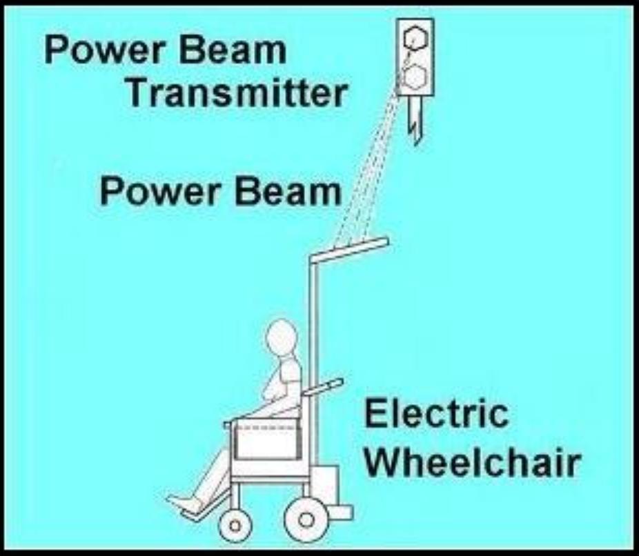
on-board energy storage unit or simply power the electronic device directly with minimal storage.Wireless power transmission will be the next generation wireless technology. This system allows the recharging of any battery powered (or any other on-board energy storage device: flywheel, ultra-capacitor, fuel cell, etc.) appliance, electronic product or gizmo without a hardwire connection to a power source, but rather simply 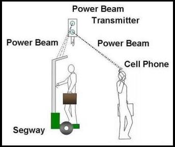 replenished via a wireless power beam cleanly, safely, and with no physical connections. This is a means by
which electronic, electrical and/or portable electric power devices, recreation equipment, appliances,
civil/military search and rescue equipment, etc., can be powered or recharged.
replenished via a wireless power beam cleanly, safely, and with no physical connections. This is a means by
which electronic, electrical and/or portable electric power devices, recreation equipment, appliances,
civil/military search and rescue equipment, etc., can be powered or recharged.This could also include medical devices, which cover all types of monitoring equipment to allow freer movement by the patient. And in the unique case for electric wheelchairs, the person would never have to worry about losing a charge on his battery. The Segway (shown at left) will have an unlimited life and distance with power transmitters along its route to ensure maximum speed and balance throughout operation. Other applications could include electrical appliances in the home. Remove a new popcorn popper from its shipping box, set the popper on the counter in close proximity to a wall mounted power transmitter, and turn on the device. No plug or cord with which to mess. Purchase a new television set, place it on the floor in close proximity to the power transmitter and cable outlet, and all connections are made wirelessly. The ARC can be used in rural areas to power water pumps for farm animals, or telephone switching stations to ensure communication during storms when power lines are down. The utility and practicality become endless for this new power resource.
For more information, please CONTACT US.
|
||
 |
Thermoelectric Catalytic Power Generator
Approximately 80% of the energy consumed in an IC-engine powered vehicle leaves as waste heat, and of the
lost energy in the exhaust, 20% is as unburned hydrocarbons which are combusted in the catalytic converter (CC).
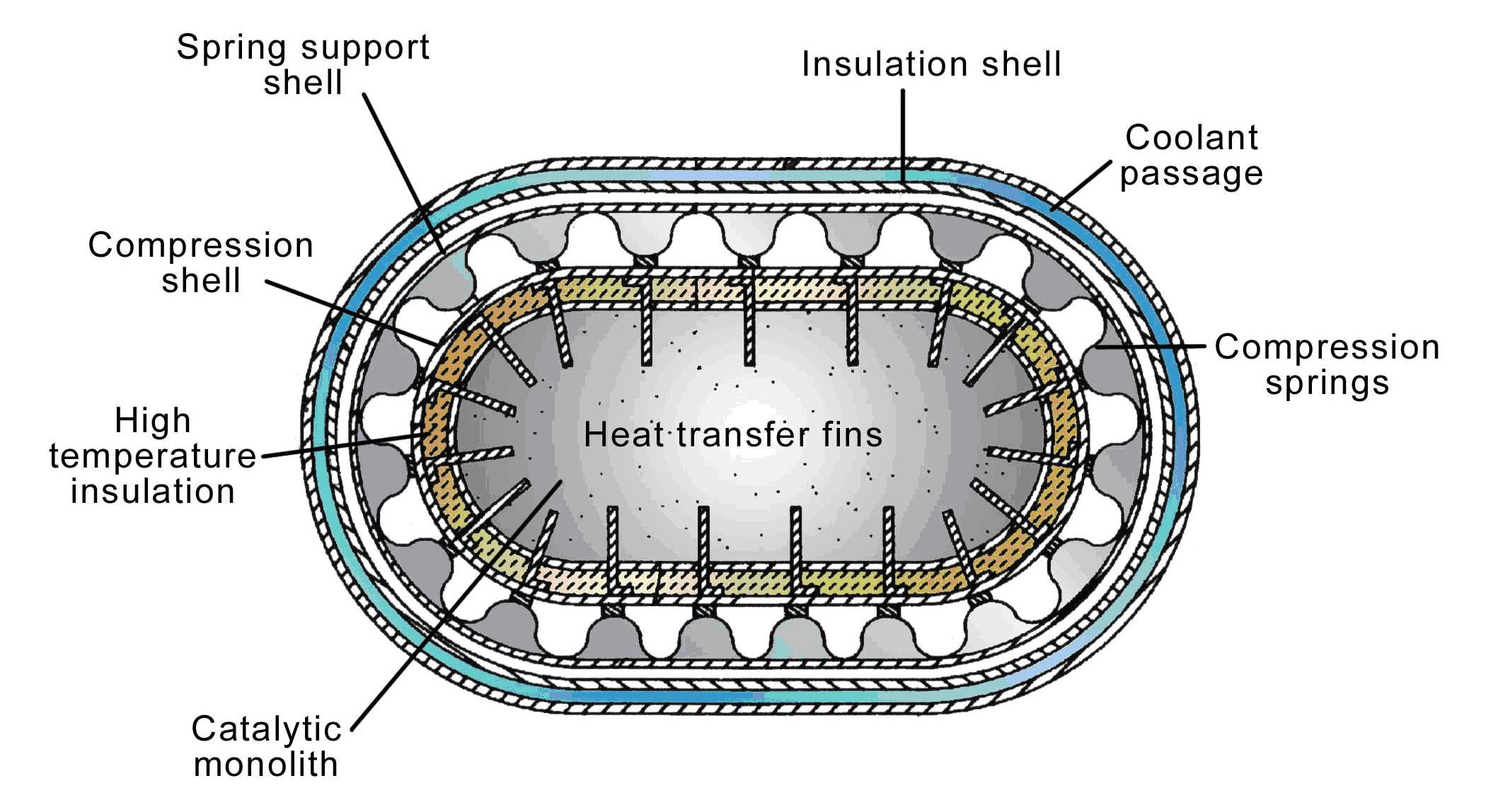
The Thermoelectric Catalytic Power Generator, or Thermo Cat Generator, utilizes the waste energy in the CC
to increase vehicle mileage 15% to 36%, depending upon the size of the vehicle, driver habits, terrain, etc.
This device is currently being marketed by
Millennium Marketing Group, Ltd,
of Overland Park, KS, and you may see their
description by doing the following: After clicking on the website hot button, type into
the box the patent number 5968456. The description website is
Patentbase.com.Inside the catalytic converter is the ideal location in the vehicle exhaust to capture the waste heat because of the tempered temperature swings which occur there compared with the large swings which take place in the rest of the exhaust system. Although some have claimed the temperature inside the CC may be excessive, insulation, controlled cooling, heat shields, etc., can all be employed to ensure the environment in the CC is suitable for the thermoelectric generators to maximize their output.
For more information, please CONTACT US.
|
|
|
BATTERY COOLER Quick Charge Battery with Thermal Management
In most secondary (rechargeable) electrochemical battery applications, internal heat build-up is a detriment to the
operation of the battery. The batteries provide electric power for remote and portable equipment, but thermal
management is needed to reduce damaging thermal build-up inside the battery, which will reduce battery life, cause
damage to internal components, and increase the operating cost of the electrical device. For example, the
life of a lead-acid battery is halved for every ten degrees that the battery operates over the normal
operating temperature. The waste heat is produced well in the bowels of the battery, and due to the geometric
design of a typical battery, the heat is not amenable to easy removal from within the battery.
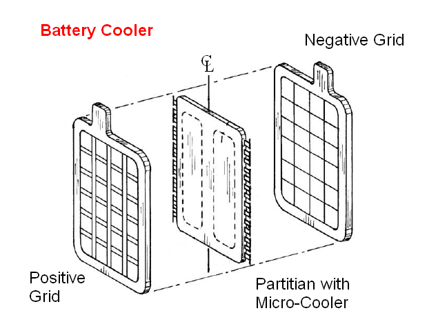
Therefore the Quick Charge Battery scheme has been developed where a solid state cooler is installed well inside the battery where the heat is produced. Here the heat is removed at the point of generation, cooling the battery more quickly and effectively. Research has shown that a cooling system inside a Ni-Zn battery, which generates the lion's share of its heat during rapid discharge, can be discharged at a higher rate by a factor of over two without thermal damage to battery components. Similarly, in a lead-acid battery where the primary heat production occurs during recharge, charging time can be cut in half. Therefore the efficacy of the internal cooler has been demonstrated theoretically; now a prototype is needed.
For more information, please CONTACT US.
|
 |
|
|
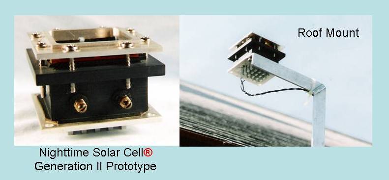
Nighttime Solar Cell®
The Nighttime Solar Cell® has been developed to produce electrical energy both day and night as a
stand-alone device or in conjunction with daytime solar panels. The original concept is based on the ancient
Egyptians’ ability to produce ice in the desert at night. Standing water in a deep hole exposed to a clear
nighttime desert sky would freeze, even in mid-summer. The phenomenon also accounts for the formation of frost on the windshield
of an automobile on a clear night when the ambient temperature is well above freezing, and why vineyards must protect ripening grapes from
frost damage even when the temperature does not go below freezing. Hence the genesis for the Nighttime Solar
Cell® was the concept of using the nighttime sky or, more correctly, deep space (nominally at 4K)
as a thermal sink, while using the ambient air as the thermal source.
 The earth's atmosphere is transparent to upwards of 80% of the infrared (IR) thermal energy in the 8micron
to 13micron spectral band, thus allowing the free movement of thermal energy from the earth's surface into
space. About one-third of the total spectral emissive power in the ambient temperature
range between 270K and 290K occurs in this band in which the Nighttime Solar Cell® is
designed to function.
The earth's atmosphere is transparent to upwards of 80% of the infrared (IR) thermal energy in the 8micron
to 13micron spectral band, thus allowing the free movement of thermal energy from the earth's surface into
space. About one-third of the total spectral emissive power in the ambient temperature
range between 270K and 290K occurs in this band in which the Nighttime Solar Cell® is
designed to function.The driving force that creates the temperature difference across the heat engine or thermoelectric generators (TEGs) is the net radiative heat flux between the flat plate inside the evacuated chamber and deep space, as seen through the spectral window. Research shows that the Nighttime Solar Cell® panel arrays will provide about one-fourth the electric power at night (12-hour period) that solar panels can produce during the day, typically when electrical energy requirements are less, using the same array surface area, or larger areas can be used to bring the electrical output more in line with solar panel requirements. The Nighttime Solar Cell® panels can be used in conjunction with any new or existing PVC installation to produce electric power at night, thus providing renewable energy 24 hours a day, increasing system reliability.
For more information, please CONTACT US.
|
||
|
Earth Cooler®
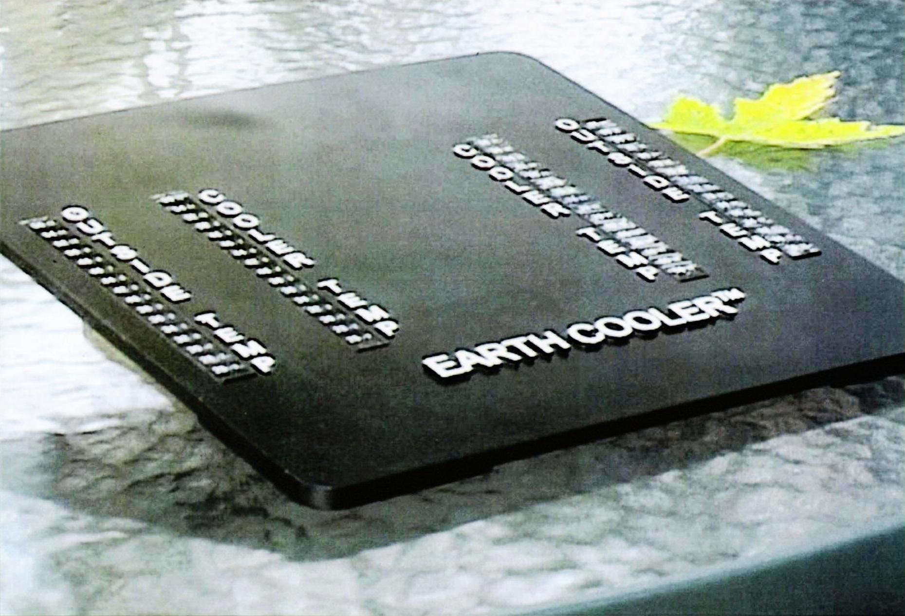
The Earth Cooler® is a patent pending, trademarked product that has been developed to offset and/or reverse the effects of global warming.
This is a device that can be mass produced easily and sold anywhere to anyone who has a desire to help reduce the effects of thermal pollution on our
environment. Particularly for today's children who are inundated with environmental issues at home and in school, this product provides a means to offset
the effects of thermal pollution due to their energy-hungry habits, as well as those of their parents. Indeed, this is a product to be used by children, hobbyists,
environmentalists, tinkerers, etc., of all ages.
This is a very unique application of the well-known laws of physics to combat the effects of global warming in the environment. Whether one believes in global warming or not is not the issue with the Earth Cooler®. The product will offset global warming in the atmosphere. This same phenomenon surrounds our daily lives and affects the things we do (see Nighttime Solar Cell® description above). The Egyptians made ice in the desert thousands of years ago utilizing these same laws of physics, and studies show that ice can be made much more cheaply in the southwestern United States using this same phenomenon rather than the vapor compression systems that are used today. So the physical laws of nature that drive the Earth Cooler® are all around us and indisputable. The Business Plan shows a $300,000 investment will realize a 50% ROI over five years, and is available upon request.
For more information, please CONTACT US.
|
 |
|
|
Static Mixer
Static Mixers are a widely used disposable plastic device for blending multi-component resins, epoxies,
dental impression materials, medical casting compounds, etc., where a less efficient, more expensive product
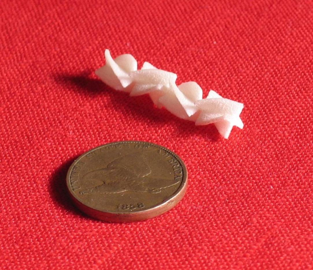
is used today than the new product developed here. This new device has four mixing blades instead of the
standard two-bladed mixers now available. Therefore this new product can mix the components in half the
mixing length, causing less waste of sometimes very expensive materials (typically those used in the medical
field, where doctors may be reluctant to use the old device). This reduced waste will increase the demand
for the new product because hand mixing is used in many cases to save expensive components.
 The mixing length is halved; therefore the effort needed to push the compounds through the device is also reduced,
easing the strain on manually operated mixers. The new mixers are produced in a less expensive continuous process
while the current mixers are made in a labor-intensive batch process. The continuous process product is better
for automatic assembly in secondary operations needed for as-sold finished product. Therefore
the new product is less expensive to make and more convenient to use in secondary operations.
The mixing length is halved; therefore the effort needed to push the compounds through the device is also reduced,
easing the strain on manually operated mixers. The new mixers are produced in a less expensive continuous process
while the current mixers are made in a labor-intensive batch process. The continuous process product is better
for automatic assembly in secondary operations needed for as-sold finished product. Therefore
the new product is less expensive to make and more convenient to use in secondary operations.Multi-component substances typically placed in a hand-held dispenser are pressed through the static mixer to blend into a single compound, which is then dispensed continuously wherever and whenever needed. This product is widely used by the medical profession (MDs and dentists), homeowners, tradesmen, industry, electronics firms – many people and professions use the Static Mixers. A working model of the four-paddle is shown. The part was made from Nylon® using the Rapid Prototyping SLS process and can be used to prove the effectiveness of the mixer in most types of compounds.
For more information, please CONTACT US.
|
||
|
Vehicle Remote Charge
System Operation: Initially, all vehicles have limited pollution-free on-board energy storage.
When the stored energy gets below a preset limit, the vehicles’ electronic system sends out a request
signal to replenish the used energy. Local power transmitting units, called pods, mounted on
stand-alone poles, existing cell towers or power utility poles,
are strategically placed along bus routes to ensure enough power is available to keep the buses moving.
A local pod receives the bus’ request signal and interprets the vehicles’ need for more “fuel”, an electronic
linkage or “handshake” is established, and the wireless power beam is sent to the bus to keep it moving.
When on-board energy storage is “full”, energy transmission is stopped. If the wireless power beam is interrupted
by a pigeon or tree branch, energy transmission is stopped. But with the bus' request signal still activated, the
electronic link-up is reactivated and more energy is sent.Safety: The power beams are sent as small energy bundles that must be acknowledged as received on the vehicle before more energy is transmitted. The energy bundles are sized so small that if one were to strike a human being, animal, or inanimate object, the amount of energy would be so little that it would be harmless. The path that the transmitted power traverses is constantly monitored electronically to prevent any harm to animate or inanimate objects. Many inherent safety features make the power network safer to operate than any competing systems, including today’s hydrocarbon fueled vehicles. Communication: The electronic link-up between the moving vehicles and the pods will provide a unique and convenient means to keep the driver abreast of weather and traffic conditions. When energy pods become prevalent enough, passengers will be able to maintain constant, uninterrupted communication with the internet. Communication also plays a primary role in safe operation of the system. The moving vehicle, when recharge is required, constantly transmits a guidance beacon for the power transmitting unit to follow. The power beam targets the origin of the guide beacon, which is located in the center of the power receiver. Therefore this line of sight tracking by the power beam on the moving vehicle ensures the safe transmission of energy for recharging. This point-to-point transmission of the power beam eliminates damaging wayward microwave energy. Regulations: The FCC controls what travels through the airways in the US. Currently there are no bandwidths assigned to wireless power transmission, nor have suitable power levels been established. These are issues a discerning government must address as the technology matures. Clean, reliable energy is available today for transportation. The US government must now allow it to become a part of the economy. Conclusion: The development of wireless power transmission in transportation will be a multi-billion dollar industry and will benefit most the region of the country that has the foresight to initiate the technology. Atlanta, Seattle, Boston, Dallas, Chicago, Hartford… any one of these cities could become the engineering hub for transportation in the 21st century.
For more information, please CONTACT US.
|
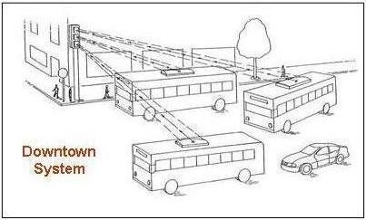
Downtown System: Typical system operation is shown on a busy downtown street where several buses enter
an intersection at the same time, and all on-board energy storage systems are recharged simultaneously as required.
Cross-communication is not a problem with the encoded power-communication signals.
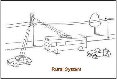
Rural System: System operation can be extended into suburban and even rural areas. With the
increased usage of the VRC and advent of energy pods, especially conveniently mounted on telephone poles, private
automobiles
can use the system as well. This will aid in the cost of adding more pods to the system, reducing pollution
further, and add to the usage of this wireless power beam as a renewable energy source.
|
|
| HOME | TECHNOLOGIES | INVESTORS | TECH PAPERS | LICENSING | Ron's BLOGGING | CONTACT US |
PARISE RESEARCH TECHNOLOGIES 101 Wendover Road • Suffield, Connecticut 06078 U.S.A. Tel: (860) 668-4599 • Fax: (860) 668-TECH • rjp@parisetech.com Site Design: rjparise@hotmail.com © Ronald J. Parise 2006 |